How a wing generates lift remains one of the most argument-inducing subjects in all aerodynamics, at least among pilots. What isn't commonly known, though, is that scientists have well understood the process for close to 100 years, and there is no debate within the scientific community.
When evaluating any potential explanation for lift, there is one important concept to keep in mind which will help you cut through the smoke: nature only has
two ways for a fluid to transmit a force to an object:
- pressure
- friction
Pressure is merely the sum total of the random motion of the atoms of a fluid. The more atoms that bounce off an object, and the faster they move, the greater the pressure felt by the object. Pressure acts perpendicular to the surface of the object.
Friction is due to the viscosity of the fluid. Yes, air has viscosity, even though it's very low compared to fluids such as molasses, or even water. Friction acts parallel to the surface over which the air flows.
So no matter what you hear about the "true" cause of lift, in the end, unless those causes can create a pressure or friction changes around the airfoil, they can have no effect on lift at all.
Now, even though technically friction can contribute to lift, it should be apparent that its contribution is small, as indicated in this diagram:

Since friction acts parallel to the surface, there are only two small areas in which friction acts in the vertical direction. Not enough to matter, so it's ignored.
So the only possible source for the forces to produce lift are the pressure differences around the airfoil. What we need to achieve looks something like this:
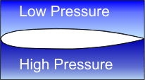
Now, one way of demonstrating the concept is by placing a disk that fits tightly in a cylinder and then evacuating the air above the disk, like so:
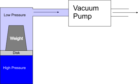
This creates a pressure difference between the top and bottom that produces a net force that lifts the weight. However, for generating lift on a wing, we could not evacuate the air fast enough to keep the surrounding air from rushing in, at least with this method.
The Bernoulli Equation
The Bernoulli equation offers another potential for lowering the pressure on the top of the wing, if we can figure out how to use it:

The Bernoulli Equation says that the sum of static pressure and dynamic pressure is always the same. If you increase the dynamic pressure, then static pressure must go down; if dynamic pressure goes down, then static pressure goes up. If we assume that the density of the air remains the same, the only way to change dynamic pressure is via changing the velocity.
One way to think of the Bernoulli Equation is that it says that the total energy of an airstream is a constant, since energy can never be created or destroyed. The static pressure is potential energy per unit volume of air and the dynamic pressure is the kinetic energy per unit volume. You can convert one to the other, but the total energy is a constant.
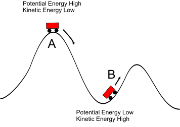
The Bernoulli Equation acts like a roller coaster, as in the picture below. Car A is at the top of a hill; it has converted its velocity into altitude and arrives at the peak with high potential energy, but low kinetic energy. Momentarily, it will convert the potential energy (altitude) back into kinetic energy as it moves to the position of car B.
Now, the classic way to use the static pressure to speed up the air is a Venturi, as shown below:

Can we use the Venturi Effect to make the air go faster over the top of the airfoil? Let's put an airfoil into the airstream and find out:
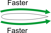
Putting an airfoil into the airflow does indeed cause the Venturi effect to kick in. The airfoil impedes the flow of air, acting as one side of the Venturi, and the atmosphere above the airfoil cannot "bump up" in order to accommodate the air trying to make a detour. It speeds up because it must.
The problem is that the airflow speeded up on
both sides of the airfoil, creating the exact same pressure drop. They cancel either other out and there is no pressure difference between the top and bottom of the airfoil that we need for lift.
The Magnus Effect
One hint as to the proper direction is indicated in something called the "Magnus Effect." Consider a cylinder placed in an airflow:
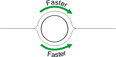
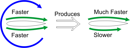
As you can see, it behaves pretty much like the airfoil above; the air speeds up on both sides of the cylinder, so no net lift is generated. But look what happens we start rotating the cylinder clockwise:
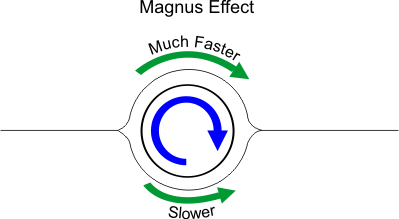
The rotating cylinder drags the air above along with it, speeding it up, but below the cylinder, the rotation fights against the airflow, slowing it down. The net result is a positive amount of lift.
Although the Magnus Effect isn't a practical means of generating lift on a wing, it does suggest that imparting some overall rotation to the airflow in addition to the freestream flow could produce lift. Our goal, then, is to somehow produce this situation:
Circulation
It turns out than when we place an airfoil in an airflow at an
angle of attack, we get exactly the rotational effect that we're looking for, and it's called
circulation.
No Viscosity
If air had no viscosity, the flow of air around an airfoil would look like this:

As you can see, there is a normal stagnation point on the leading edge, but the rear stagnation point is on the top. In order for the rear stagnation point to be there, the airflow must be like this:

This can't happen, except at very low airspeeds. The airflow simply cannot follow the rapid change in direction that would be required to negotiate the sharp trailing edge, and the airflow separates from the surface into a tight vortex:

This vortex, called the
starting vortex is carried away down stream, but it leaves behind another vortex that has the same quantity of rotation, but in the opposite direction. The follow graphic uses the analogy of cogs to show how the starting vortex creates its opposite around the airfoil:
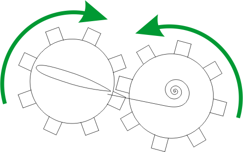
So what we're left with is a permanent vortex, called the
bound vortex that speeds up the air on the top of the wing, and slows it down in the bottom, like this:
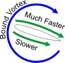
The air never flows backwards along the bottom of the airfoil as the bound vortex seems to show. Instead, it adds to the freestream; since the freestream is faster, the net result is movement in the freestream direction, just slower.
Is It Real?
Photographs of the airflow over a wing made visible by such techniques as smoke show that the initiation of lift creates the starting vortex, just as the theory shows. The bound vortex is evident as it spills over the wing tips into the familiar wingtip vortices. Each change in angle of attack is accompanied by a new starting vortex.
So, yes, real world evidence supports that circulation theory is more than just a mathematical tool that works.
Anderson, John D., Jr., Fundamentals of Aerodynamics. McGraw-HIll, New York, 2001.
Carpenter, Chris. Flightwise: Principles of Aircraft Flight. Airlife Publishing Ltd, Shrewsbury, UK. Copyright 1996.
Kundu, Pijush K. and Ira M. Cohen. Fluid Mechanics. Academic Press, San Diego, CA. Copyright 2002.
The greatest rate of climb in an airplane occurs at a velocity where the greatest excess power occurs, as shown by the orange points in the graph below.
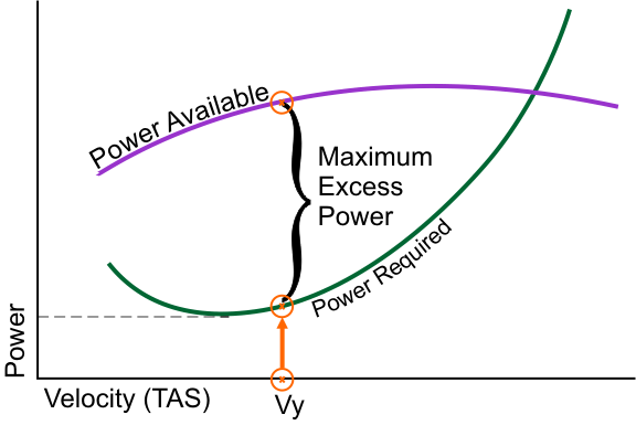
Figure 1
At higher altitudes, the less dense air causes the Power Required curve to rise and rotate to the right, as shown below in figure 2. This occurs because
- Induced drag increases at every airspeed because the less dense air requires a greater angle of attack to ensure that lift = weight;
- Parasite drag decreases at every airspeed because less dense air provides a smaller frictional force at every airspeed.
Since induced drag predominates at low airspeeds, total drag within this speed range increases. At faster airspeeds, where parasite drag predominates, the total drag is reduced.
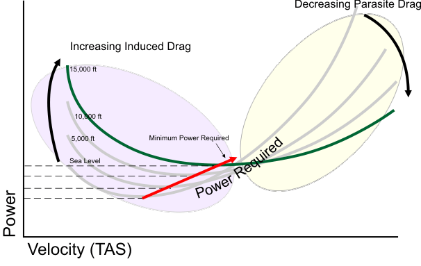
Figure 2
This shift in the Power Required curve causes the point of minimum drag to
increase and
shift right, meaning that it will occur at a higher true airspeed.
Increased altitude also changes the Power Available curve, but at least this change is straight-forward. At any given airspeed, there will simply be less power available because of the less dense air, as shown in figure 3. The point of maximum power available will still occur at the same airspeed because the shape of the curve does not change, only its height.
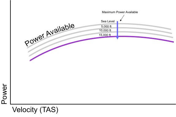
Figure 3
We can now put figures 2 and 3 together to see what happens the Vy, which will be the airspeed where there is the greatest difference between Power Available and Power Required. This chart is shown below in figure 4.
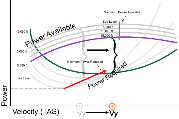
Figure 4
What this chart shows is the Vy shifts to the right, due to the tilting of the Power Required curve. This conclusion contradicts what we know from real airplanes, where Vy
decreases with altitude.
How can we explain this result?
Important Point:
These charts are plotted using true airspeed, but Vy is normally provided as an indicated airspeed.
So these charts so far aren't very useful in explaining why Vy in
indicated airspeed will decrease with altitude. We can, however, make these charts more useful by plotting the same data in indicated airspeeds, rather than true airspeeds, and this is shown below in figure 5.
The main differences between this chart and the one in figure 4 are
- The power required curves merely moves up when plotted in indicated airspeeds, it doesn't tilt right
- The power available curve now shifts left as well as down, instead of just moving down like it did when plotted in true airspeeds.
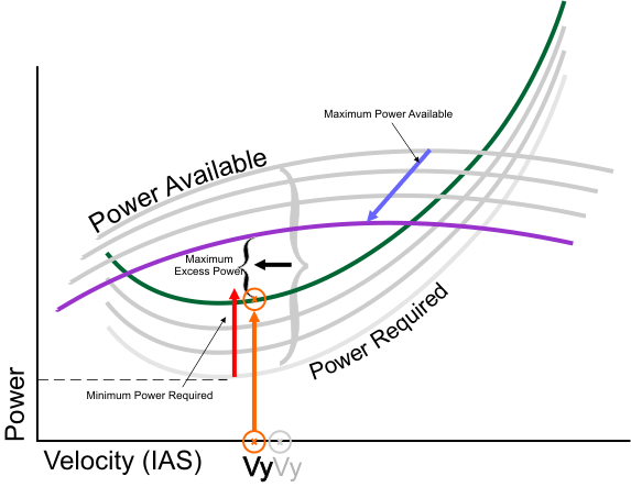
Figure 5
These differences cause the point of maximum excess power to move left, as we would expect.
Executive Summary
- Maximum rate of climb occurs at the airspeed where the power available exceeds power required by the greatest amount.
- The indicated airspeed airspeed at which this occurs decreases with altitude because the power available curve shifts left when plotted by indicated airspeed.
- The maximum rate of climb decreases both because of the reduced power available and increased power requirements.
One interesting idea that sometimes shows up in discussions of turning flight is that of an "unloaded" turn, a turn in which you bank, but avoid the load factor normally incurred by the bank by not simultaneously increasing the AoA by pulling back on the yoke.
The advantage of this technique, so proponents say, is that you get the turn but avoid the increase in stall speed associated with a loaded turn. So there is a free lunch after all.
Well, not really. There are two problems with this technique:
- It's primarily the load factor which is responsible for the increased rate of turn in a bank, so you're giving that up, and
- Without increasing the AoA, the airspeed of the aircraft will increase while the bank is held until the load factor ends up where it should have been based on your bank angle.
So is there any value at all in the technique? Let's run some numbers, using this diagram and formula as the basis of our calculations:
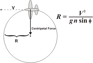
Figure 1
In the table below, the first three entries in the table are "true banked turns" where the AoA is increased as the bank is entered to keep the airspeed the same. I use the term "true banked turn" to refer to a turn in which your turn rate is appropriate for your angle of bank. When this is not the case, such as in a slip or skid, the apparent gravity inside the airplane not acting through the center of your body, but at an angle, tending to slide you along the seat towards the inside or outside of the turn. The present situation is exactly the same as a slip, where the turn rate is less than what you'd expect based on the bank angle.
The entry highlighted in yellow is the unloaded turn. I show two values for some entries in the unloaded turn row, because the airspeed increases steadily during the maneuver.

Table 1
Here are some interesting observations regarding the calculations:
- The smallest turn radius occurs with the 60° true banked turn, as you'd expect, but in this case, the aircraft stalls.
- The next best turn radius occurs with the 45° bank, with a 11 knot margin over the stall speed.
- The unloaded 60° banked turn has the third best performance, but the aircraft will steadily accelerate, generating an increasing load factor and increasing stall speed. Interestingly, the turn radius does not change as the load factor increases, because the increased velocity exactly compensates for it.
The unloaded turn doesn't get the expected performance because it only generates half of the centripetal force that a true banked 60° turn would. So in terms of safety and performance, you're better off maneuvering at the proper airspeed for the bank angle you've chosen.
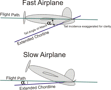
Stalling the horizontal stabilizer can happen in icing conditions where leading edge ice causes the airflow to separate at a less negative AoA than normal. What isn't intuitive is that the recovery procedure is to
pull back on the yoke, rather than pushing forward like a stall of the main wing. The reason is that the tailplane is at a larger negative AoA when the main wing is at a smaller AoA (faster), and vice versa. To reduce the negative AoA on the horizontal stabilizer, you must
increase the AoA on the main wing. The reason should be clear if you view the orientation of the horizontal stabilizer to the relative wind in each of the two situations, being fast and being slow:
A critical piece of information for interpreting the above diagram is that the AoA on an airfoil is normally measured as the angle between the relative wind and the chordline of the
unaugmented airfoil, meaning no flaps, and the elevator (and rudder, ailerons) are simply plain flaps. So deflecting the elevator by definition has no effect on the location on the chordline.


